I3T Manual
This manual serves as a comprehensive guide to using the I3T tool, focusing on its key features and functionality. It helps users navigate the application, understand its interface, and master tools for 3D transformations and scene composition. For first-time users, we recommend following the introductory tutorials (I3T Introduction and Advanced I3T functions) for a hands-on start.
User interface
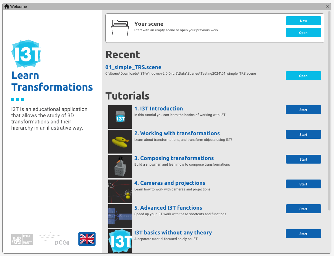
The program begins with the Start Window, which allows you to choose between tutorials, opening an existing scene, or creating a new one. Once selected, the program enters the Workspace mode, consisting of two main windows.
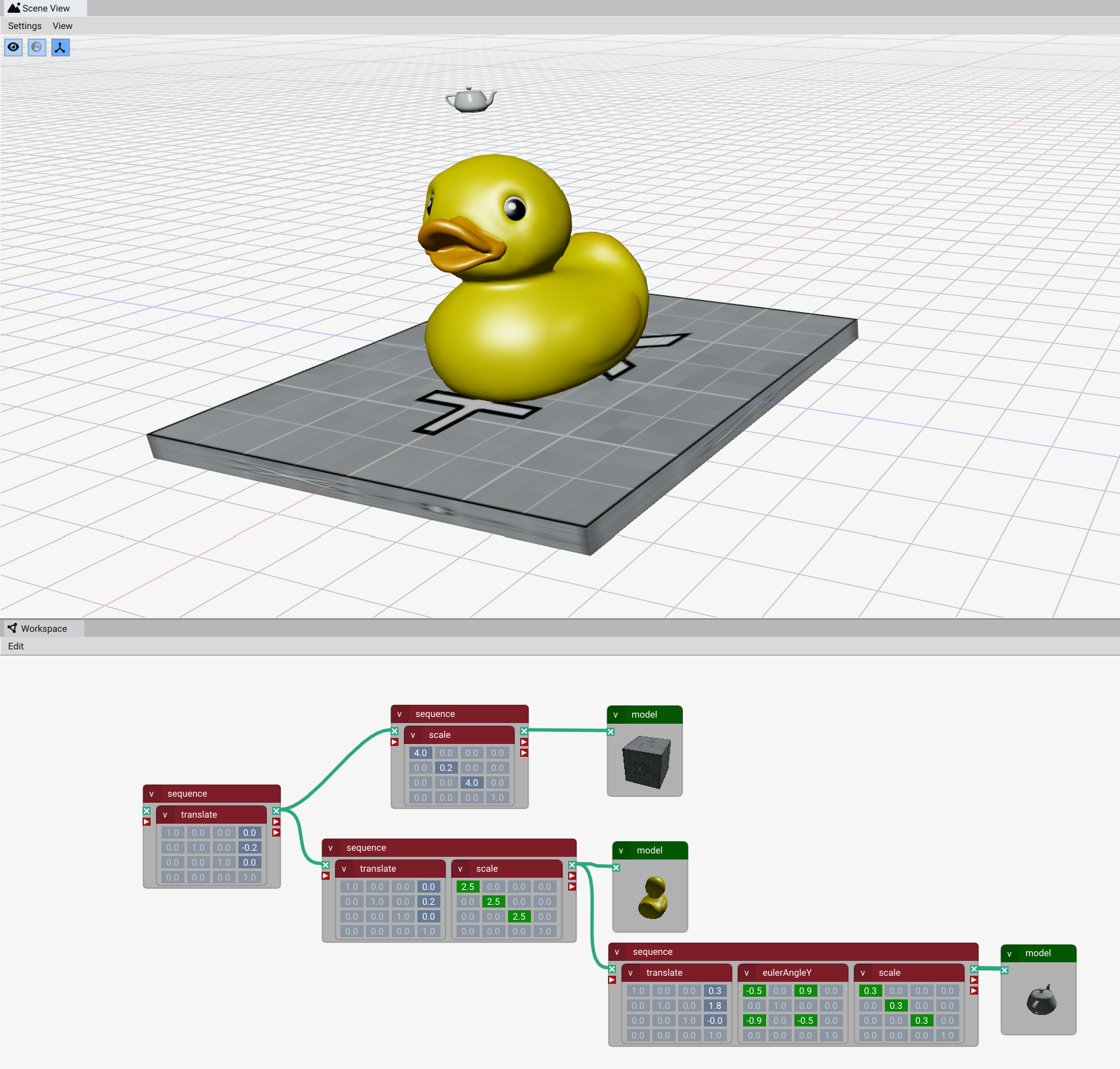
In the Workspace window, the user prepares individual transformations and models and plugs them into the scene graph (in its simple version). Users can also add cameras and preview what they see.
The basic building blocks in the Workspace are connectable nodes (including models) and matrices that need to be inserted into sequences for connection. These appear as small rectangles called nodes, which contain titles and content.
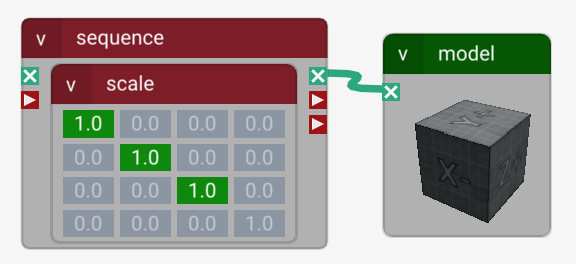
Matrices function as nodes with a 4x4 grid of real numbers. Matrices affect objects when you combine them in the scene graph and place them into a larger node called a sequence.
Sequences have inputs and outputs marked by small icons.
The greatest strength of the I3T tool lies in its interactivity. Users can:
- Dynamically build Scene Graphs by connecting sequences with inserted matrices
- Directly modify matrix values and see the immediate impact in the Scene View window
- Observe camera positions and their viewing frustums
The resulting 3D representation of the structure generated by the graph is immediately visible in the 3D view in the Scene View window.
Controls
The application is primarily controlled through:
- Mouse interactions (click-drag, right-click menus)
- Main menu bar (global application functions)
- Window-specific menus (contextual tools in each workspace)
- Keyboard shortcuts (for quick access to functions)
Windows List
- Start Window - Contains tutorials teaching basic controls, practices and recent scenes
- Tutorials Window - Interactive guides for learning core functionalities
- Workspace - Main window for building scene graphs using nodes and matrices
- Scene View - Displays real-time 3D visualization of the scene graph from the Workspace
Window-Specific Menus
Workspace
- Edit: Select all nodes
- Add: Open node-insertion context window
- View:
- Zoom: To selection / All nodes / Reset
- Grid: Toggle (Dots/Squares display)
Scene View
- Settings:
- Scene: Toggle World Space Lighting
- Manipulators: Gizmos (move/rotate/scale) + size adjustment
- MSAA: Anti-aliasing (Off/2x/4x/8x)
- Highlight: Quality (Ultra → Lowest)
- Transparency: WBOIT toggle + adjustments
- Shaders: Reload without restart
- View:
- Camera: Orbit/Trackball mode, Smooth scroll, FOV
- Grid & Axes: Plane toggles (XZ/XY/YZ), visibility controls
- Navigation: Preset views (Numpad), Focus on selection/scene
- Visibility: Toggle objects/grid/cameras/frustums
Main bar
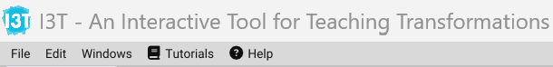
The I3T application has a standard main menu in its top.
File Menu
- New: Creates a new scene.
- Open: Opens an existing scene file from the
Data/Scenes/directory. (Shortcut: Ctrl + O) - Recent: Displays a list of recently used scenes for quick access.
- Save: Saves the current scene. (Shortcut: Ctrl + S)
- Save As: Saves the current scene under a new name.
- Manage Models: Import new models into I3T. Supported formats include
.gltf(with.bin) and.glfb. - Exit: Closes the application.
Edit Menu
- Style Editor: Opens the style editor for customizing the application theme.
- Preferences:
- Configure the model preview in the Workspace.
- Set the highlight color for selected models in the Scene View.
- Adjust the grid settings in the Scene View.
Windows Menu
- Start Window: Opens the start menu window.
- Tutorial Window: Opens tutorial window with link to start window.
- Scene View Window: Toggles visibility of the Scene View window.
- Workspace Window: Toggles visibility of the Workspace window.
Tutorials Menu
- Start Window: Opens the start menu window.
- Reload: Reloads the current tutorial.
Help Menu
- About: Displays information about the application, including its version and credits.
Shortcuts
| Action | Shortcut |
|---|---|
| Copy Component | Ctrl + C |
| Paste Component | Ctrl + V |
| Duplicate Component | Ctrl + D |
| Cut Component | Ctrl + X |
| Select All Components | Ctrl + A |
| Invert Selection | Ctrl + I |
| Undo | Ctrl + Z |
| Redo | Ctrl + Y |
| Zoom To All Components | Ctrl + Alt + A |
| Zoom To Selected Components | Ctrl + Alt + S |
| Open Scene | Ctrl + O |
| Save Scene | Ctrl + S |
Workspace
The Workspace window is where scenes are assembled. You can add, connect, and manipulate nodes to create the desired transformations and models.
Adding Nodes
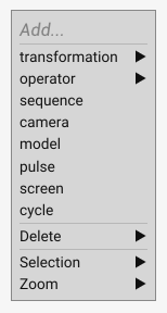
- To add node, right-click anywhere in the Workspace to open the context menu.
- Main node types include:
- Transformation: For moving, rotating, scaling, and projections (e.g.,
translate,rotate,scale,projection). - Operator: Performs operations on matrices, vectors, quaternions, and floats (e.g.,
normalize vec3,matrix inversion,quat * quat). - Sequence: Groups transformations and defines their order.
- Model: Represents 3D objects like cubes.
- Camera: Adds cameras for custom scene views.
- Other Nodes: Includes Pulse, Screen, and Cycle for specific use cases.
- Transformation: For moving, rotating, scaling, and projections (e.g.,
Selecting Nodes
Selecting nodes in the Workspace is done through:
- Click selection:
- L-Click: Select/deselect single node
- SHIFT + L-Click: Multi-select nodes
- Box selection:
- Partial Selection (Green Box):
- Click outside nodes and drag right to left
- Nodes partially covered by green box are selected
- Full Selection (Blue Box):
- Click outside nodes and drag left to right
- Only nodes fully covered by blue box are selected
- Partial Selection (Green Box):
Selected nodes appear with orange outline.
Connecting Nodes
Nodes function like functions, with inputs and outputs. Connect nodes using wires to form a scene graph:
| Icon | Name | Description |
|---|---|---|
| Matrix multiplication | Combines matrices through multiplication (only operation that transforms matrix data) | |
| Matrix input/output | For connecting matrices. | |
| 3D vector input/output | For connecting vector values. | |
| 4D vector input/output | For connecting 4D vector values. | |
| Float input/output | For connecting float values. | |
| Screen output | For cameras specifically to output what they "see." | |
| Quaternion input/output | For connecting quaternion data. | |
| Pulse input/output | For triggering cyclic or time-based operations. | |
Colored wires visualize connections, showing the flow of data through the scene graph. Each type of connection is specific to its data type (e.g., matrices, vectors, floats, quaternions, or pulses).
Transformations
Transformations are always inserted into sequences. The order can be arbitrary. A typical order is Translation, Rotation, Scaling (TRS).
How to Add Transformations to a Sequence
Transformations are always inserted into sequences. The order can be arbitrary, though a typical order is Translation → Rotation → Scaling (TRS).

- Select the Transformation Node:
- Locate the transformation node in the Workspace Menu.
- Drag and Drop:
- Click and hold the transformation node with the left mouse button.
- Drag the node to the desired position inside a sequence.
- Release the mouse button to drop the node into the sequence.
- Sequence Multiplication:
- Transformations in a sequence are multiplied from left to right, meaning the order matters.
- For example, placing
Translatefollowed byRotatewill first move the object, then rotate it around the new position.
Modifying Values
- Adjust Values with Dragging:
- Click and hold the value in the matrix using the left mouse button.
- Drag the mouse to increase or decrease the value.
- Hold SHIFT for faster changes or Alt for precise slower adjustments.
- Edit Values Directly:
- Double-click on the value in the matrix to open an input box.
- Type the desired value and press Enter to confirm.
- Use the Context Menu:
- Matrix label click: Controls synergies and decimal places
- Disable Synergies: Adjust scaling independently for each axis.
- Float value click: Opens Choose Value menu with common constants
- Matrix label click: Controls synergies and decimal places
Tracking
The Tracking feature allows you to observe how transformations are applied step-by-step in a sequence by interpolating matrices over time.
- It gradually applies part of the transformation matrices, starting from the world space origin (no transformation, identity) and ending with the complete set of transformations used. Identity starts from the world space origin.
- This explains the paradigm of how to read the sequence of transformations – either as the transformation of the coordinate frame or as the transformation of the model in the world frame.
- The area of sequences is split into active and skipped parts of transformations by a yellow line.
How to Enable Tracking
- Right-Click on a Sequence Node:
- In the Workspace, right-click on a sequence node to open the context menu.
- Choose one of the following options:
- Start Tracking from Left: Tracking begins with the first transformation in the sequence.
- Start Tracking from Right: Tracking begins with the last transformation in the sequence.
- Tracking Copy:
- A copy of the model appears in the Scene View, allowing you to visualize the transformations interactively.
- Note: tracking works only on nodes with a connected model
How Tracking Works
- Tracking helps to visualize how transformations are applied in sequences by interpolating between transformation matrices step by step.
- A yellow line represents the tracking cursor, the applied parts of the matrices remain visible, and the skipped parts are grey. Pressing the right arrow key moves the line forward. The left arrow key moves the line backward.
- The complete transformation is the same. The difference is in understanding combined transformations - if we read the matrices left-to-right or right-to-left.
- Shows how transformations progressively modify the coordinate system before applying them to the object.
- Tracking begins with the first transformation in the sequence. The coordinate frame is identical to the world space frame.
- The tracking line starts at the leftmost position of the sequence.
- Each transformation is applied sequentially, gradually altering the coordinate system.
- For example, with a TRS sequence:
- First, the coordinate system is translated, moving the reference point.
- Next, it is rotated, changing the orientation of subsequent transformations.
- Finally, the coordinate frame is scaled.
- The object is drawn in this translated, rotated, and scaled coordinate frame.
- Shows how transformations progressively modify the coordinate system before applying them to the object.
- Tracking begins with the last transformation in the sequence. It shows how transformations directly affect the transformed object in global space.
- The tracking line starts at the rightmost position of the sequence.
- Each transformation is applied in a global coordinate system, altering the partially transformed model.
- For example, with a TRS sequence:
- First, the object is scaled in global coordinates.
- Next, the scaled object is rotated in global coordinates.
- • Finally, the rotated and scaled object is translated in global coordinates, shifting its final position.
Start Tracking from Left
Start Tracking from Right
Stopping Tracking
- Right-Click on the Sequence Node:
- To stop tracking, press Esc or right-click on the sequence node again and select Stop Tracking from the context menu.
- The tracking copy and yellow line will be removed.
Camera and Screen
The Screen none is a node that allows you to visualize the output of the camera. The screen can be resized by dragging one corner.
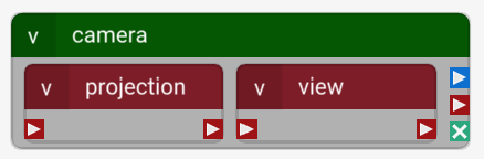
The Camera node allows you to add a camera to your scene. It contains two sequences:
- Projection: A container for projection matrices (e.g., orthogonal or perspective).
- View: A container for the view matrix, which positions and orients the camera.
The Camera node has three outputs:
| Icon | Name | Description |
|---|---|---|
| Screen Output | Displays what the camera sees (connect to a Screen node). | |
| Matrix Copy Output | Outputs the resulting matrix for further manipulation. | |
| Multiplication Output | Allows multiplication with other matrices. |
To visualize what the camera sees:
- Add a Screen node to the Workspace.
- Connect the camera’s Screen Output to the Screen node.
- Adjust the screen size by dragging its red corners.
Projection Matrix
- Creates a flat view (e.g., blueprints), where object size remains constant regardless of distance.
- Use disable synergies to adjust bounds independently.
- Mimics human vision, where objects appear smaller as they move farther away.
- Commonly used for realistic 3D scenes requiring depth perception.
View Matrix
- Eye vector: Camera position.
- Center vector: Point the camera looks at.
- Up vector: Direction considered "up" for the camera.
The lookAt matrix cannot be edited directly but is controlled through these vectors.
Theory
Operators
Operators in I3T perform calculations and manipulations on various data types, such as matrices, vectors, quaternions, and floats. They are categorized into groups based on the type of operation they perform. Operators can be added through the Workspace menu and connected to other nodes. 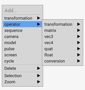
Transformation Operators
Transformation Operators:
These operators are used to modify the position, rotation, and scale of objects in 3D space.
| Operator | Description |
|---|---|
| Translate | Moves objects along the X, Y, and Z axes. |
| EulerAngleX | Rotates objects around the X-axis. |
| EulerAngleY | Rotates objects around the Y-axis. |
| EulerAngleZ | Rotates objects around the Z-axis. |
| Rotate | Generic rotation in 3D space. |
| Scale | Scales objects along the X, Y, and Z axes. |
Projection Operators:
These operators generate matrices for viewing transformations. Their names correspond to the names used in OpenGL.
| Operator | Description |
|---|---|
| Orthogonal | Creates an orthogonal projection matrix. |
| Perspective | Generates a perspective projection matrix. |
| Frustum | Constructs a frustum projection matrix. |
| LookAt | Creates a view matrix based on eye, center, and up vectors. |
Matrix Operators
| Matrix Operator | Description |
|---|---|
| Matrix | Basic matrix initialization and operations. |
| Inversion | Computes the inverse matrix. |
| Transpose | Flips the rows and columns of the matrix. |
| Determinant | Calculates the determinant of the matrix. |
| Mat * Mat | Multiplies two matrices together. |
| Mat * Vec4 | Multiplies the 4D vector by the matrix from the left (Mv, as usual in OpenGL right hand coordinate frame). |
| Vec4 * Mat | Multiplies the 4D vector by the matrix from the right (as usual in DirectX left hand coordinate frame). |
| Mat + Mat | Adds the two matrices together. |
Vec3 Operators
| Vec3 Operator | Description |
|---|---|
| Vec3 | Creates or manipulates a 3D vector. |
| Show Vec3 | Displays the components of a 3D vector. |
| Vec3 x Vec3 | Computes the cross product of two 3D vectors. |
| Vec3 · Vec3 | Calculates the dot product of two 3D vectors. |
| Vec3 + Vec3 | Adds two 3D vectors together. |
| Vec3 - Vec3 | Subtracts one 3D vector from another. |
| Float * Vec3 | Multiplies a 3D vector by a scalar value. |
| Normalize Vec3 | Converts a 3D vector to unit length. |
| Length(Vec3) | Computes the magnitude of a 3D vector. |
| Mix Vec3 | Blends two 3D vectors together. |
Vec4 Operators
| Vec4 Operator | Description |
|---|---|
| Vec4 | Creates or manipulates a 4D vector. |
| Vec4 · Vec4 | Calculates the dot product of two 4D vectors. |
| Vec4 + Vec4 | Adds two 4D vectors together. |
| Vec4 - Vec4 | Subtracts one 4D vector from another. |
| Float * Vec4 | Multiplies a 4D vector by a scalar value. |
| Normalize Vec4 | Converts a 4D vector to unit length. |
| Perspective Division | Applies perspective division to a 4D vector forming a 3D vector [x,y,z] in Euclidean spce from a 4D homogeneous vector [xw, yw, zw, w]. |
| Mix Vec4 | Blends two 4D vectors together. |
Quaternion Operators
| Quaternion Operator | Description |
|---|---|
| Quat | Creates or manipulates a quaternion. |
| Quat(Float, Vec3) | Generates a quaternion using a float and a 3D vector. |
| Quat(Angle, Axis) | Constructs a quaternion from an angle and axis. |
| Quat(Vec3, Vec3) | Creates a quaternion between two 3D vectors. |
| Quat → Float, Vec3 | Converts a quaternion to a float and a 3D vector. |
| Quat → Angle, Axis | Converts a quaternion to an angle and axis representation. |
| Float * Quat | Splits a quaternion (x,y,z,w) to a float w and a 3D vector (x,y,z). |
| Quat * Quat | Multiplies two quaternions together. |
| Quat → Euler | Converts the quaternion to Euler angles. The order of rotations is R = RzRyRx, for rotation of point p by R computed as Rp. |
| Euler → Quat | Converts Euler angles (Rx, Ry, Rz) to a quaternion, representing the rotation R = RzRyRx. |
| Slerp | Performs spherical linear interpolation between two quaternions. |
| Long Way Slerp | Performs spherical linear interpolation with an inverted path. |
| Lerp | Performs linear interpolation between two quaternions. |
| Quat Conjugate | Computes the conjugate of a quaternion. |
| QVQ* | Performs quaternion-vector multiplication. |
| Inverse Quat | Computes the inverse of a quaternion. |
| Normalize Quat | Converts a quaternion to unit length. |
| Length(Quat) | Computes the magnitude of a quaternion. |
Float Operators
| Float Operator | Description |
|---|---|
| Float | Creates or manipulates a floating-point value. |
| Clamp Float | Restricts a float to a specified range. |
| Float * Float | Multiplies two floating-point values. |
| Float / Float | Divides one floating-point value by another. |
| Float + Float | Adds two floating-point values. |
| Float ^ Float | Raises one float to the power of another. |
| Mix Float | Blends two floating-point values together. |
| Sin & Cos | Computes the sine and cosine of an angle. |
| Asin & Acos | Computes the arcus sine and arcus cosine of a value. |
| Signum | Determines the sign of a floating-point value. |
Conversion Operators
| Conversion Operator | Description |
|---|---|
| Mat → TR | Converts the matrix to translation and rotation components. |
| TR → Mat | Constructs a matrix from translation and rotation components. |
| Mat → Vec4 | Converts the matrix to four 4D column vectors. |
| Mat → Quat | Converts a matrix to a quaternion. |
| Mat → Floats | Converts a matrix to floating-point values. |
| Vec4 → Mat | Create a matrix from four 4D column vectors.. |
| Vec4 → Vec3 | Reduces a 4D vector to a 3D vector. |
| Vec4 → Floats | Converts a 4D vector to floating-point values. |
| Vec3 → Mat | Create a 4x4 affine matrix from four 3D column vectors, leaving the last row 0,0,0,1. |
| Vec3 → Vec4 | Form a 4D vector from a 3D vector and a float. |
| Vec3 → Floats | Converts a 3D vector to floating-point values. |
| Quat → Floats | Converts a quaternion to floating-point values. |
| Floats → Mat | Creates a matrix from floating-point values. |
| Floats → Vec4 | Creates a 4D vector from floating-point values. |
| Floats → Vec3 | Creates a 3D vector from floating-point values. |
| Floats → Quat | Creates a quaternion from floating-point values. |
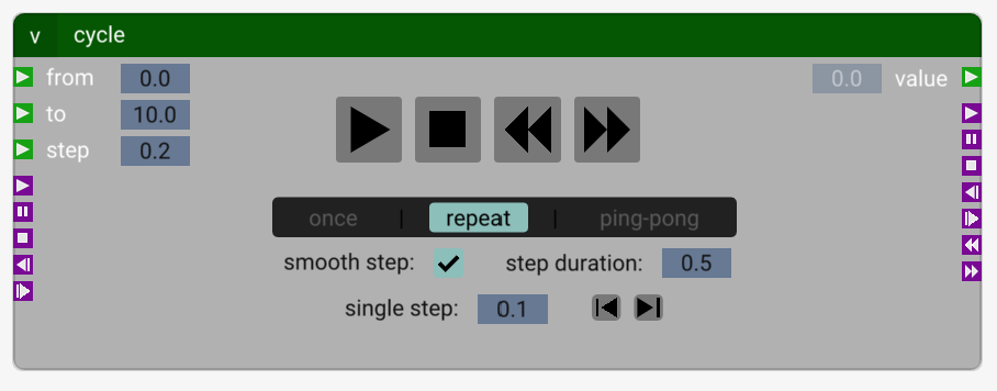
Cycle
The Cycle node facilitates cyclic or time-based operations, providing control over value transitions, looping behaviors, and timing. It enables the creation of animations, repetitive movements, and smooth transitions within your scene.
Inputs and Outputs
Inputs
![]() Float Inputs:
Float Inputs:
These inputs control the numerical values for the cycle's progression.
| Icon | Input | Description |
|---|---|---|
| tbd | From | Start value of the cycle. |
| tbd | To | End value of the cycle. |
| tbd | Step | The increment or decrement applied at each step. |
<p><img src="../Docs/assets/pulse.png?raw=true" width="20" height="20" alt=""><strong> Pulse Inputs:</strong><br>These inputs trigger actions or changes within the cycle. They correspond to pressing the cycle control buttons</p>
<table>
  <thead>
    <tr>
      <th><strong>Icon</strong></th>
      <th><strong>Input</strong></th>
      <th><strong>Description</strong></th>
    </tr>
  </thead>
  <tbody>
    <tr>
      <th>tbd</th>
      <td><strong>Play</strong></td>
      <td>Begins or resumes the cycle.</td>
    </tr>
    <tr>
      <th>tbd</th>
      <td><strong>Pause</strong></td>
      <td>Temporarily halts the cycle without resetting values.</td>
    </tr>
    <tr>
      <th>tbd</th>
      <td><strong>Stop</strong></td>
      <td>Ends the cycle and resets the value to <strong>From</strong>.</td>
    </tr>
    <tr>
      <th>tbd</th>
      <td><strong>Prev</strong></td>
      <td>Subtracts the single-step value from the cycle value. Does not stop the cycle.</td>
    </tr>
    <tr>
      <th>tbd</th>
      <td><strong>Next</strong></td>
      <td>Adds the single-step value to the cycle value. Does not stop the cycle.</td>
    </tr>
  </tbody>
</table>
Outputs
![]() Float Output:
Float Output:
This output provides the current value of the cycle.
| Icon | Output | Description |
|---|---|---|
| tbd | Value | The current value of the cycle. |
<p><img src="../Docs/assets/pulse.png?raw=true" width="20" height="20" alt=""><strong> Pulse Outputs:</strong><br>These outputs signal the pressing of the cycle control buttons and specific cycle events.</p>
<table>
  <thead>
    <tr>
      <th><strong>Icon</strong></th>
      <th><strong>Output</strong></th>
      <th><strong>Description</strong></th>
    </tr>
  </thead>
  <tbody>
    <tr>
      <th>tbd</th>
      <td><strong>Play</strong></td>
      <td>Signals when the Play button is pressed, and the cycle starts.</td>
    </tr>
    <tr>
      <th>tbd</th>
      <td><strong>Pause</strong></td>
      <td>Signals when the Pause button is pressed, and the cycle paused.</td>
    </tr>
    <tr>
      <th>tbd</th>
      <td><strong>Stop</strong></td>
      <td>Indicates that the Stop button has been pressed, the cycle stopped, and its value reset to From.</td>
    </tr>
    <tr>
      <th>tbd</th>
      <td><strong>Prev</strong></td>
      <td>Indicates that the <strong>Prev</strong> button has been pressed.</td>
    </tr>
    <tr>
      <th>tbd</th>
      <td><strong>Next</strong></td>
      <td>Indicates that the <strong>Next</strong> button has been pressed.</td>
    </tr>
    <tr>
      <th>tbd</th>
      <td><strong>Begin</strong></td>
      <td>Indicates that the cycle value reached the value of <strong>From</strong> (anyhow, via buttons or during repeat or ping-pong cycling).</td>
    </tr>
    <tr>
      <th>tbd</th>
      <td><strong>End</strong></td>
      <td>Indicates that the cycle value reached the value of <strong>To</strong> (anyhow, via buttons or during repeat or ping-pong cycling).</td>
    </tr>
  </tbody>
</table>
Parameters
- From: Starting value of the cycle.
- To: Ending value of the cycle.
- Step: Determines the increment or decrement applied to the value at each step.
- Smooth Step: Enables smooth transitions throughout the Step Duration.
- Step Duration: Time (in seconds) for each step.
- Single Step: Triggers one step manually, moving the value up or down once.
Playback Modes
- The Cycle node offers three playback modes:
- Once: The cycle runs from From to To in steps and stops.
- Repeat: The cycle loops, restarting at From after reaching To.
- Ping-Pong: The cycle alternates direction, moving from From to To, then back to From, and so on.
Controls
- Start/Pause: Toggles between starting and pausing the cycle.
- Stop: Ends the cycle and resets the value to From.
- Skip to Start: Immediately sets the value to From. If the cycle is running, it continues.
- Skip to End: Immediately sets the value to To. If the cycle is running, it continues.
Scene View
The Scene View provides a real-time 3D visualization of your scene, allowing you to see the effects of transformations, manipulations, and node connections directly as you build them in the Workspace.
Manipulators
Manipulators are tools for adjusting transformations like translate, rotate, and scale using a 3D manipulation in the Scene View. These manipulators can only modify transformations existing in the workspace—they cannot create new transformations or connect them to models.
Visual Indicators in the Scene View
- Orange Outline: Highlights the currently selected model in the Scene View.
- Blue Outline: Appears when a transformation selected in the Workspace affects a model in the Scene View. This blue outline serves as an indicator and not as a selection.
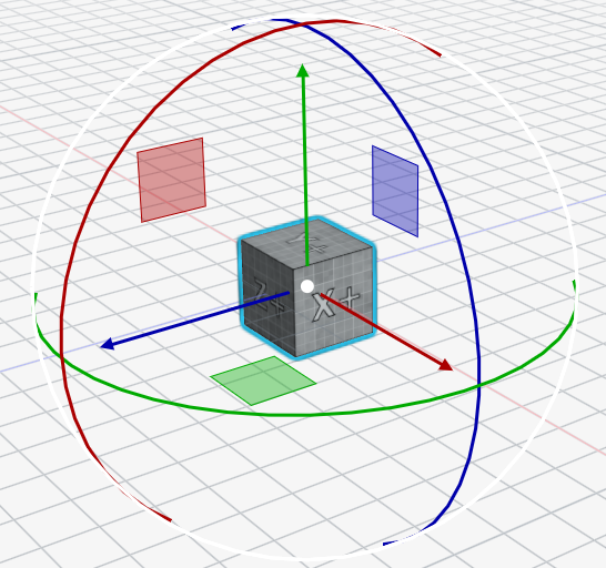
Types of Manipulators
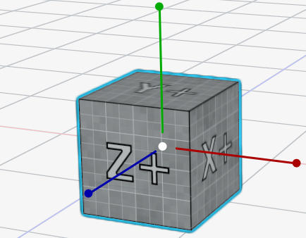
Translate Manipulator
- Shown as colored arrows (Red: X-axis, Green: Y-axis, Blue: Z-axis).
- Drag the arrows to move the object along a specific axis.
Rotate Manipulator
- Appears as colored circles around the object (Red: X-axis, Green: Y-axis, Blue: Z-axis).
- Click and drag a circle to rotate the object around the corresponding axis.

Scale Manipulator
- Displayed as colored dots (Red: X-axis, Green: Y-axis, Blue: Z-axis) ) at the end of colored segments.
- Drag the squares to scale the object along a specific axis.
Using Manipulators
Enable Manipulators
- Manipulators are displayed for selected transformations in the Workspace, not automatically for selected models in the Scene View.
- To enable manipulators, select a transformation in the Workspace.
- Manipulators can also be toggled off from the menu bar:
- Settings > Manipulators: Disable manipulators through the Scene View menu bar.
- Toolbar: Use the buttons located below the main menu bar to toggle manipulators.
Adjusting Values
- Changes made via manipulators are reflected directly in the selected transformation matrices in the Workspace window and also next to the model in Scene View.
Tutorials
In I3T, tutorials are an interactive way for new users to become more familiar with the program while learning important theory about I3T features.
A total of nine tutorials are available. Five of them focus on the basics, while the remaining four focus more on advanced features.
Before working with the program, we recommend to try to go through at least the basics (5 introductory tutorials), but if you already know the basics of transformations, matrix multiplication, projection matrices, and cameras, you may want to take the alternative tutorial, which skips the theoretical parts of the introductory series and concentrates on the I3T user interface only.
If the user already knows what they are doing, they can try exercises (the last two tutorials), that test the user's ability to handle complex tasks with more vague instructions.
Technical manual
GUI
Themes
The colors and other size properties of the GUI is determined by the current application Theme. There are multiple themes to choose from and can be switched and edited at runtime via the Style Editor window. One default theme is always loaded called the 'Classic' style. This object is initialized in code in the Theme::createDefaultClassic() method. Other themes are loaded from .yml files in the Data/Themes directory.
A Theme (GUI/Theme/Theme.h) object contains key-value pairs of style properties (colors (ImVec4) and sizes (floats, ImVec2)). These style properties overwrite the standard Dear ImGui style properties and specify the visual theme of the application. The style properties are also queried from various parts od the GUI codebase and used locally to style specific components or used outside of Dear ImGui.
Each additional theme loaded from the .yml files using GUI/Theme/ThemeLoader.h is derived from the 'Classic' theme and initially contains the properties set by the Theme::initClassicProperties() method. These properties are then partially or fully overwritten by the style properties present in the styles .yml file.
Adding a Theme style property
To add a style property, the following must be done in Theme.h/.cpp:
- Create a style property key in one of the enums depending on the type (EColor, ESize, ESizeVec2).
- Set a default value for the 'Classic' theme in
initClassicProperties(). - Add a human-readable key name in the
Theme::initNames()method. - (optional) Do something with the style variable value at Theme init in the
Theme::apply()method. Usually this would be overwriting an existing ImGui style variable with it.
DIWNE
See the DIWNE documentation.
Tutorials
Main classes for handling tutorials are TutorialWindow, StartWindow, TutorialLoader, Tutorial, an Theme
Tutorials can be accessed through the Start window, which lists all tutorials located in the Data/tutorials folder.
Tutorials are loaded from *.tut'' files using the TutorialLoader'' class, which processes all data from the source files into an instance of the Tutorial'' class. This instance will contain data in a format that can be loaded into the TutorialWindow'' class to be rendered and displayed to the user.
The *.tut source files are searched for keywords and symbols that alter the way the text is rendered, similar to the Markdown language. Appearance and form of elements created using keywords can be updated in the TutorialWindow class in the renderHint() (or render*Something*()) functions.
Styling, fonts and colors of the window are stored in the Theme.cpp and Theme.h, which can be modified to style the tutorial window and its contents.
If you need to create new tutorials, follow these instructions.
Logging
Mouse Interaction Logging
By default, mouse interaction logging is off. You can enable it by pressing F4.When enabled, the following events are logged to Logs/Mouse.log:
- Mouse position (every two seconds)
- Mouse click
- Mouse release
User Interaction Logging
By default, user interaction logging is off in Release mode but enabled in Debug mode. You can toggle or refine the logging categories using F1, F2, and F3. When enabled, the following events are logged to Logs/UserInteraction.log:
F1: Logs popup interactions, including:
- Opening a menu or popup
- Clicking on a button
- Selecting an item from a menu
F2: Logs workspace and logic interactions, including:
- Adding a Node to a workspace
- Removing a Node from a workspace
- Attaching or disconnecting a Link from a Node
- Adding a Node to a Sequence
- Removing a Node from a Sequence
F3: Logs changes to values in matrices, such as:
- Modifying a numeric value in a matrix cell
- Selecting a different model for a specific node or matrix
Additionally:
- Opening a Tutorial and changing steps in a tutorial is also logged when user interaction logging is enabled.
These logs can help developers and testers to understand user behavior, diagnose issues, or gather information for improvements.